Nullmodem.Com

Null Modem DB-25 DB-9 (Really DE-9) HD-D-sub 15 Centronics Parallel LapLink Cable UPS Serial Cables RJ-45 10Base-T Crossover Serial-to-Ethernet Keyboard Connectors USB Floppy ISA Connector PCI PCMCIA Audio Connectors Common Terms Connector Index Pro Sound JimPrice.Com


RJ-45

The RJ-45 connector is commonly used for network (Ethernet) cabling and for telephony applications.  It's also used for serial connections in special cases, as well as for audio.  Here's a look at it:
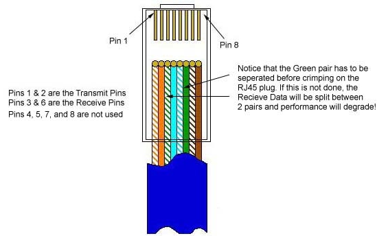
RJ-45 Connector

Pinout for Ethernet

Although used for a variety of purposes, the RJ-45 connector is probably most commonly used for 10Base-T and 100Base-TX Ethernet connections.

Pin #

Ethernet 10BASE-T
100BASE-TX

EIA/TIA 568A

EIA/TIA 568B or AT&T 258A

1

Transmit +

White with green strip

White with orange stripe

2

Transmit -

Green with white stripe or solid green

Orange with white stripe or solid orange

3

Receive +

White with orange stripe

White with green stripe

4

N/A

Blue with white stripe or solid blue

Blue with white stripe or solid blue

5

N/A

White with blue stripe

White with blue stripe

6

Receive -

Orange with white stripe or solid orange

Green with white stripe or solid

7

N/A

White with brown strip or solid brown

White with brown strip or solid brown

8

N/A

Brown with white stripe or solid brown.

Brown with white stripe or solid brown.

Because only two pairs of wires in the eight-pin RJ-45 connector are used to carry Ethernet signals, and both 10BASE-T and 100BASE-TX use the same pins, a crossover cable made for one will also work with the other.

Also, please note that it is very important that a single pair be used for pins 3 and 6.  If one conductor from one pair is used for pin 3 and a conductor from another pair is used for pin 6, performance will degrade.  See the following figure.

To learn more about Ethernet, check out Charles Spurgeon's Ethernet Reference

RJ-45 Pinout for RocketPort

The following chart shows the pinout for RJ-45 connectors used on certain RocketPort serial interface cards (manufactured by Comtrol).

Pin Name/Description
1  Request To Send
2 Data Terminal Ready
3 Ground
4 Transmit Data
5 Receive Data
6 Data Carrier Detect
7 Data Set Ready
8 Clear To Send


    Pinouts for ISDN

Here's an ISDN BRI U port pinout for a Cisco 750 series router:

Pin Function
1  Not used
2  Not used
3  Not used
4  U interface network connection (tip)
5  U interface network connection (ring)
6  Not used
7  Power (pass-through to S connector)
8  Ground (pass-through to S connector) 


The following chart shows the pinout for RJ-45 connectors used on certain ISDN S/T interfaces.  For more info, see ANSI T1.605.

Pin Color Name/Description
1  White/Orange  N/A
2  Orange  N/A
3  White/Green  Receive+
4  Blue  Transmit +
5  White/Blue  Transmit -
6  Green  Receive -
7  White/Brown   -48VDC (optional)
8  Brown  -48VDC Return (optional)


The following chart shows the pinout for RJ-45 connectors used for audio in the StudioHub wiring system. Caution - Different audio products from different manufacturers may use different pinouts. Please refer to your equipment's manual to verify the pinout. Also, see StudioHub.Com, now owned and operated by by Angry Audio for more details.

Pin Color Name/Description
1  White/Orange  L+/AES+
2  Orange  L-/AES-
3  White/Green  R+
4  Blue  GND
5  White/Blue  N/C
6  Green  R-
7  White/Brown   -15VDC (optional)
8  Brown  +15VDC Return (optional)


This page and its contents, copyright © 1996-2026, JimPrice.Com. Here's a link to our privacy statement.  If you have any questions about this page, please don't hesitate to e-mail me.  (The address should be obvious to all but spam-bots.)

This site last updated 4/13/2026