|

Floppy Drive Connector
The floppy disk interface uses what is possibly the strangest cable of all
those used in 1980s and 1990s PCs. It is similar to the legacy IDE cable in that it is usually a
flat, gray ribbon cable, with an IDC connector. It is unusual in terms of the number of connectors it
has and how it is used to configure the setup of the floppy disks in the system.
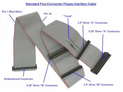
The floppy cable has 34 wires. There are normally five connectors on the
floppy interface cable, although sometimes there are only three. These are
grouped into three "sets"; a single connector plus two pairs of two
each (for a standard, five-connector cable) or three single connectors. This how
the connectors are used:
 | Controller Connector: The single connector on one end of the cable
is meant to connect to the floppy disk controller, either on a controller
card or the motherboard.
| Drive A Connectors: The pair of connectors (or single connector in
the case of a three-connector cable) at the opposite end of the cable is
intended for the A: floppy drive. This is explained in more detail below.
| Drive B Connectors: The pair of connectors (or single connector in
the case of a three-connector cable) in the middle of the cable is intended
for the B: floppy drive. |
| |
The reason that the floppy disk drive cable uses pairs of connectors for the
drives is for compatibility with different types of drives. 3.5" drives
generally use a pin header connector, while 5.25" drives use a card edge
connector. Therefore, each position, A and B, has two connectors so that the
correct one is available for whatever type of floppy drive being used. Only one
of the two connectors in the pair should be used (they're too close together to
use both in most cases anyway). The more common pin header (IDC)
connector is shown below.
The three-connector cables are found either in
very old systems or in ones where the manufacturer was trying to save a few
pennies. They reduce the flexibility of the setup; fortunately these cables can
be replaced directly by the five-connector type if necessary.
You will also notice that there is an odd "twist" in the floppy
cable, located between the two pairs of connectors intended for the floppy
drives. Despite the fact that this appears to be a "hack" (well, it
really is a hack), this is in fact the correct construction of a standard
floppy interface cable. There are some cables that do not have the twist, and it
is these that are actually non-standard! What the twist does it to change
the connection of the drive on the far end of the twist so that it is different
than the drive before the twist. This is done to cause the drive at the end of
the cable to appear as A: to the system and the one in the middle to be as B:.
Here's how it works in detail. Traditionally, floppy drives used a drive
select (DS) jumper to configure the drive as either A: or B: in the system.
Then, special signals were used on the floppy interface to tell the two drives
in the system which one the controller was trying to talk to at any given time.
The wires that are cross-connected via the twist are signals 10 to 16 (seven
wires). Of these, 11, 13, and 15 are grounds and carry no signal, so there are
really four signals that are inverted by the twist. The four signals that are
inverted are exactly the ones that control drive selection on the interface.
Here is what happens when the twisted cable is used:
| |
Line 10
|
Line 12
|
Line 14
|
Line 16
|
|
Controller Signals
|
Motor Enable A
|
Drive Select B
|
Drive Select A
|
Motor Enable B
|
|
Drive Before the Twist Sees
|
Motor Enable A
|
Drive Select B
|
Drive Select A
|
Motor Enable B
|
|
Drive After the Twist Sees
|
Motor Enable B
|
Drive Select A
|
Drive Select B
|
Motor Enable A
|
Since the signals are inverted, the drive after the twist responds to
commands backwards from the way it should; if it has its drive select jumpers
set so that it is an A: device, it responds to B: commands, and vice-versa.
One might ask why the twist was needed. In short, because it was a
big time-saver during setup back in the days when it was quite common to find
two floppy drives in a machine. Without the twist, for two
floppy drives to be used, one had to be jumpered as A: and the other as B:.
With the twist, it was possible to leave them both jumpered as B:, and whichever
was after the
twist will appear to the system as A: because the control lines are inverted.
Changing which drive is A: and which is B: is as easy as switching the
cable. In systems with only one floppy drive, only the connector after the
cable should be used. Large manufacturers, therefore, could arrange to have all of their
floppy disks configured the same way without having to pull jumpers as the PC
was assembled.
In order for this system to work, both drives must be jumpered as B: drives.
Since the floppy cable with the twist is standard, this jumpering scheme has
become the standard as well. Virtually all floppy disks that you purchase come
pre-jumpered as B: drives so that they will work with this setup.
If this whole idea sounds similar to the seldom-used cable select
protocol for IDE/ATA hard disks, that's because it is essentially the same
thing. IDE/ATA hard disks require you to change the master/slave jumpers in a similar
manner, and cable select was invented to do away with this. The difference is,
as usual, just one of inertia and history; the floppy drive system is the
standard while cable select never caught on for hard disks.
Some newer BIOSes have taken things a step further. They include a BIOS
parameter that will invert the A: and B: signals within the controller itself.
When enabled, this lets you reverse whichever drive is A: with the one that is
B:, without requiring you to even open the case. Note however that this is not
compatible with all operating systems: in particular, both Windows NT and Linux
can malfunction with this swap feature set, which can cause serious problems
when trying to install the operating system. The reason this happens is that the
swap setting only affects the way the BIOS handles the floppy drive, and
confuses operating systems that go directly to the hardware.
Apparently, there is yet another floppy cable variant out there, that is used
by some manufacturers. In this setup, there are actually two twists in the
floppy cable. The drive placed after the first twist, in the middle of the
cable, is A:, much as it is with the standard one-twist cable. The drive placed
after the second twist is B:. The second twist "reverses" the effect
of the first one and makes the connector at the end of the cable operate the
same way a drive that appears before the twist in a regular cable does.
|